
Euroskills Gdańsk 2023 Test project for the Skill 63 - Robot System Integration was about sanding various different types of painted panels.
The Basic Task consisted in sanding of 2 parts, 1 at time. These parts could be: a standard flat; a small flat and a door part.
The Turntable were subdivided in Loading area and Processing area and had to be set up electrically and pneumatically by competitors in order that it could rotate by 180° in both directions.
The part detection had to be done not by the iRVision but just with an optical sensor mounted on EOAT.
The Extended Task consisted in sanding a curve part. For this task (but also for the basic task) Cad-To-Path function was the best choice, as it's born exactly for this type of applications. If you didn't know about this function, it would take you too much time for the pattern creation. This function saves you a significant amount of time by leaving you only the "configuration" part of the pattern.
The Project doesn't end here. You had to implement a little bit more sophisticated Home-Check program before the start of the main program. You had to make it in the way that you could not damage any part of the cell even if you want.
You also had to setup the ESTOP Turntable error handling. During the rotation of the Turntable, if you press the ESTOP button it had to stop immediately. But when you release it, only if the main cycle is restarted, the robot had to memorize the direction of the last rotation for a proper cycle execution.
A small, but a particular thing was the Quick Master Position. It is a position which is used as the reference to the future Quick Mastering. In this project it could be simply the ZERO Position (in case there were no specifics) but in the reality when your robot working-space is too narrow till the point that it can't go to its ZERO, is extremely useful for the mastering, because you can redefine the reference position.
In parallel, a weighty part of the project was the HMI. As always it has to be user-friendly, contain all the necessary information about the state of the cell, comprehensible also by a not skilled operator.
As the professional, in the end you have to leave your client a clear, in contents and graphically, maintenance documentation. The operators should be able to find immediately what they need and fix everything in case of system and/or user errors even if they don't have the Digital Twin near them.
Lastly, the Digital Twin is the first and the last thing the integrator MUST do. The role of the Digital Twin is essential for the performance of the integrator. You never start to work physically in the cell before the simulation check of the layout and the reachability of the points. It's also highly useful in case you need to change any part of the cell rapidly. It allows you to check the practicability of any feature before its actual integration.
DCS is a built-in safety system that monitors and controls the motion of the robot, verifying that it operates within defined safety parameters. This function helps prevent accidents by allowing specific zones or movements to be controlled and restricted, ensuring that the robot does not operate in a way that could endanger human operators or equipment.
I prefer to create a detailed DCS where my goal is not only to protect humans from the robot, but also essential peripherals for the application. As in this project the robot has no need to move near the camera, so for this reason I reduced the working area. Whilst the I/O Board has some cables inside the working zone I created a small one.
Another aspect to work on is the STOP PREDICTION that helps predict the collision with the Safe area limits. Here you should test the movements on high-speed in order to see how far does the robot exceed the safe zone.
If the tool is too light I will force-limit the max speed in manual mode (ex. 50%). This way I compensate the inertia of the robot so it can stop in time.

The HMI (Human-Machine-Interface) is an essential part in industrial applications. HMI helps to the new, both skilled and not, operators to comprehend the functioning and the current state of the cell.
In this project there were no specific instructions on what should be created in HMI, so I created the basic pages with main info and controls regarding the application as:
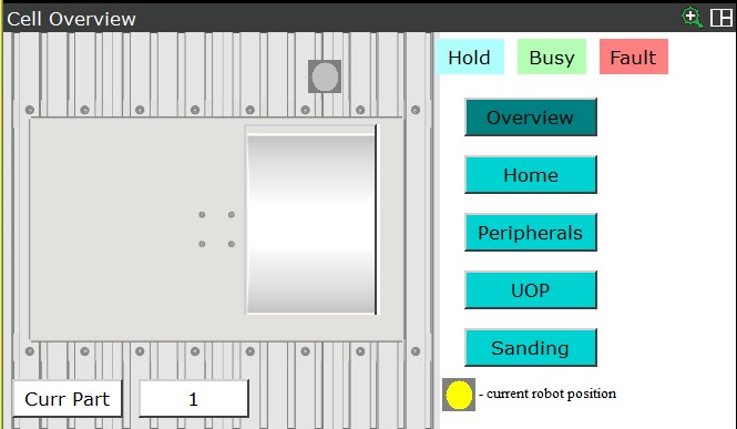
Before the main program start, there will be always a home check. In other words, usually the robot should start the program from the well defined position.
For this purpose I created a space above the turntable that gives in output the signal that tells me if the robot is inside that zone or not.
If the robot is outside, the dialog will be displayed with the instructions on how to proceed.
Otherwise if the robot is in the safe space the menu will be displayed with option on how to proceed.
Any option you choose, the confirm dialog will be displayed in order to drag operator's attention to their choices.

The Turntable is controlled by I/O. The pneumatic valve is controlled by 2 Outputs, and there are 2 sensors which are connected to 2 inputs to detect the 2 end positions.
In an Emergency, the Robot can be stopped by pressing one of the red Emergency Stop buttons on the Teach Pendant or on the Controller.
A Turntable can also be a dangerous piece of equipment, so in this case the Turntable should also stop, even if itis in the middle of a rotation.
So for this purpose I created a "background logic" program that always scanning the state of the ESTOPs and the state of the cell and memorize where the last rotation was directed.
Only when the program restarts the rotation continues.

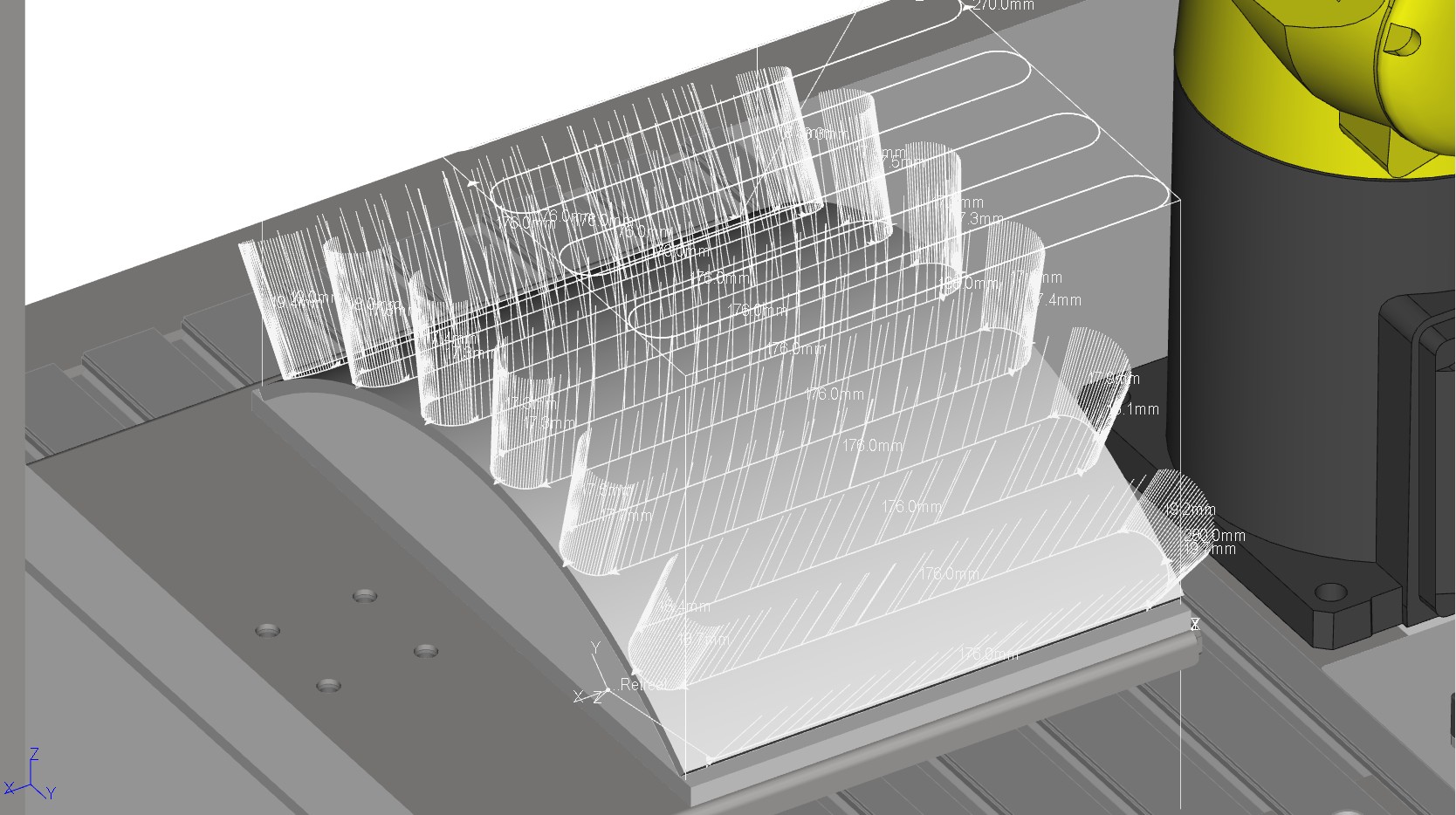
Cad-To-Path is a function that simplifies you the pattern creation. Instead of mathematical calculations it leaves you only the configuration part.
Thanks to this function (that is free) is a powerful tool which allows you to complete the movements in few minutes.
As the actual sanding is quite complicated to simulate you can't test the efficiency, but if you had the physical parts Cad-To-Path has instruments to adjust the positions quickly and even to create the reverse pattern in one-click (in case you want to do the double sanding).


.svg)
.svg)